TI-83 Teardown, Part 2
Finally getting to the pixie wrangling and commanding the LCD to display images.
Hey all!
This is a part 2 for the first segment of the TI-83 teardown, where we disassembled the calculator and started interfacing with the LCD.
Whoops! May have lied a bit last time. Before I get to the fun part (programming!) I designed small crimp bracket in SOLIDWORKS to try and, again, minimize wear and tear on the fragile ribbon cable. Am I a bit too paranoid? Maybe. Was it fun? Absolutely!
Here's what the model turned out looking like:
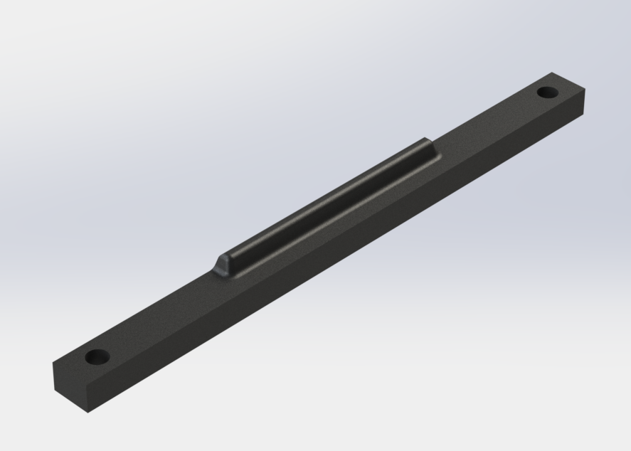
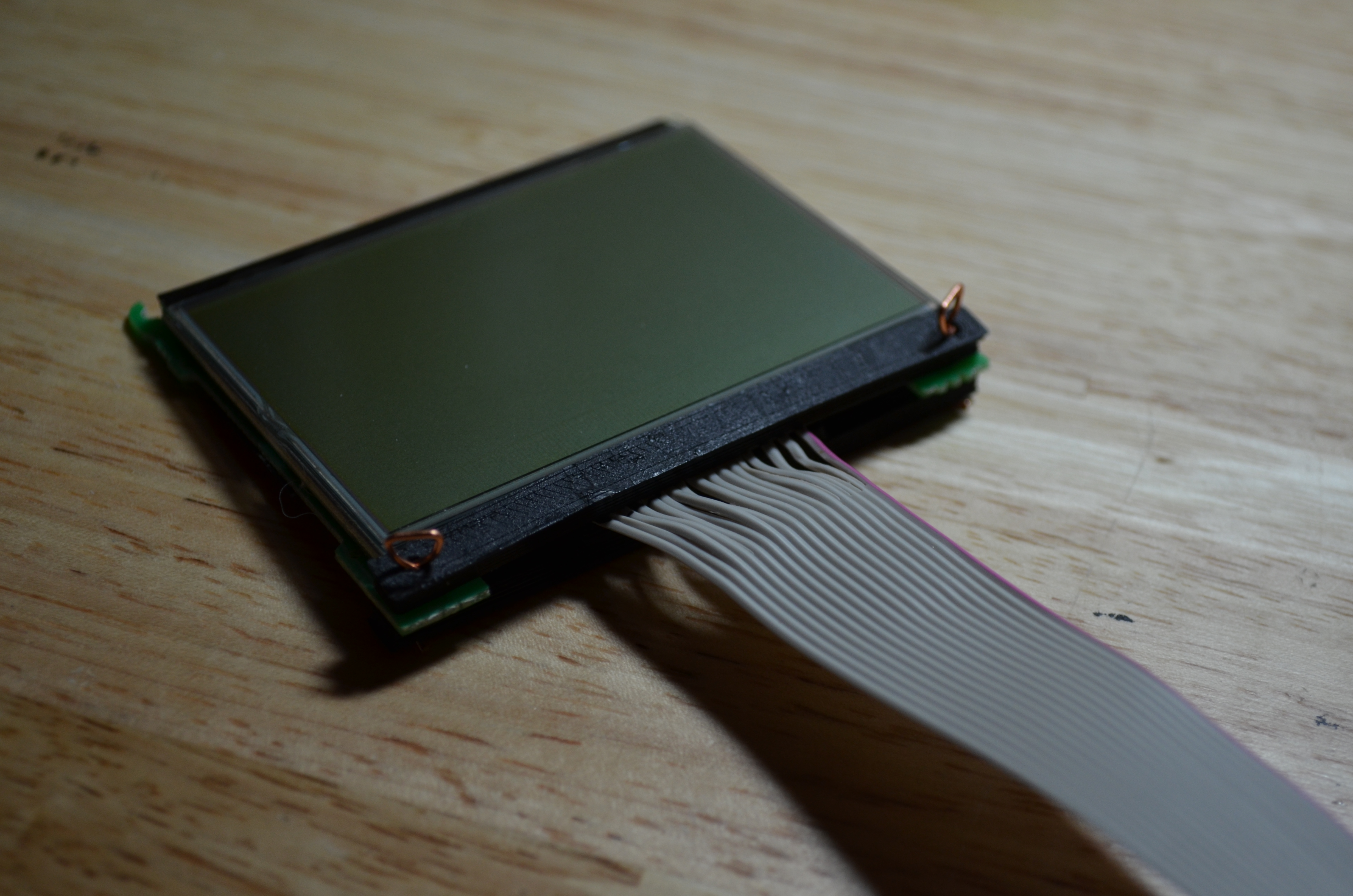
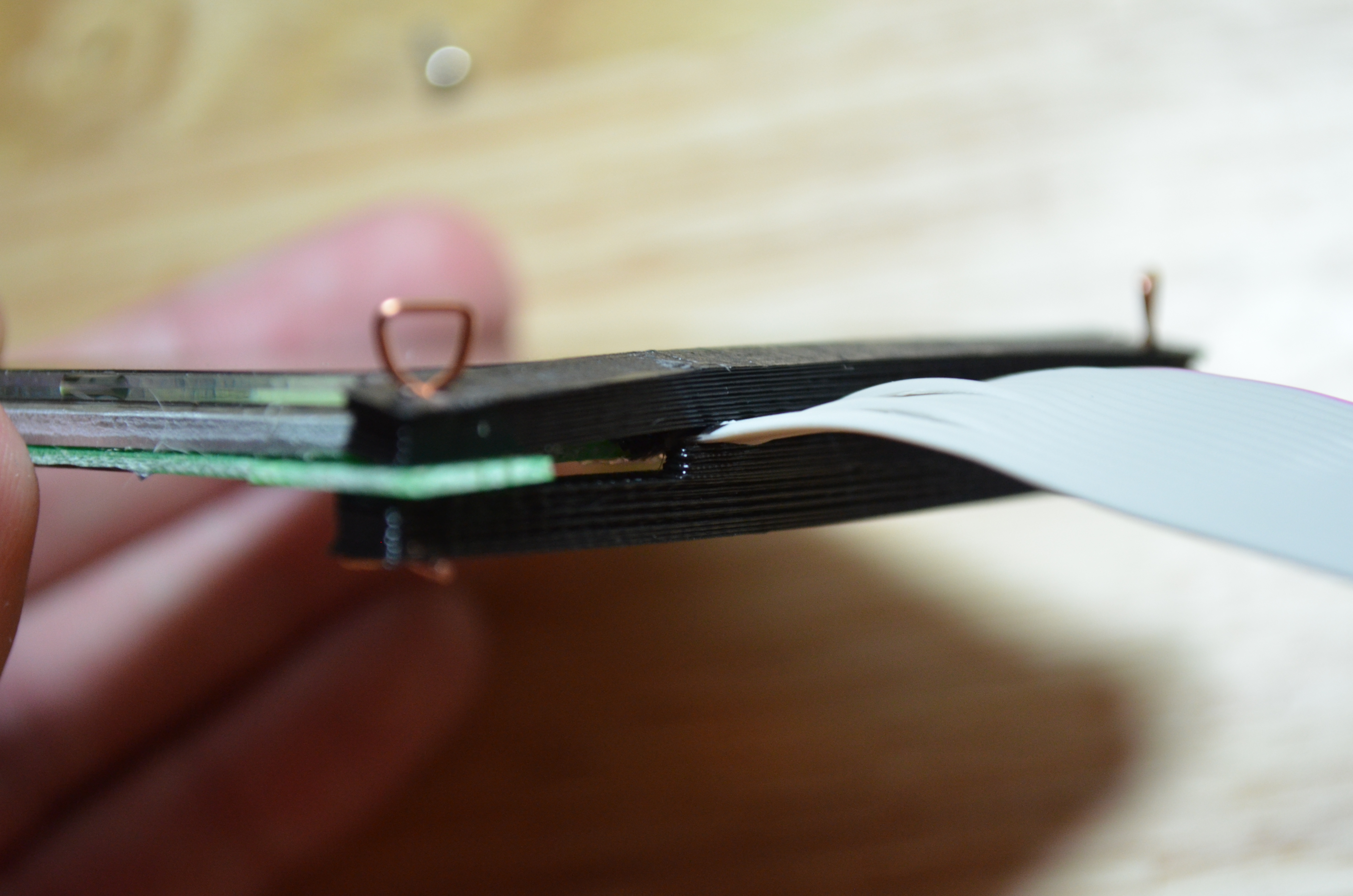
I 3D printed 2 of them and sandwiched them together around the new ribbon cable, all held together with 2 tiny cotter pins I had to make
NOW comes the fun part!
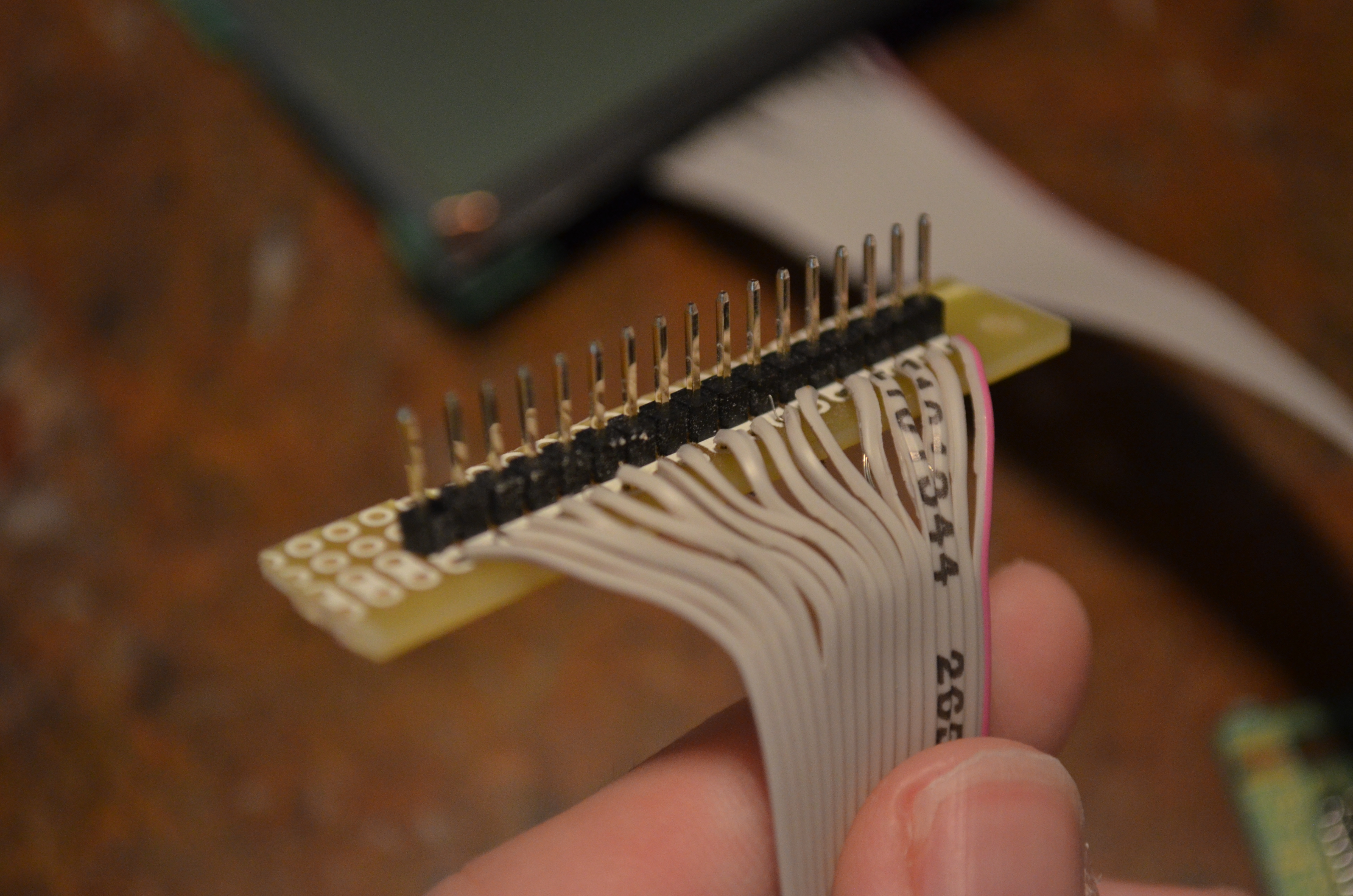
1: New connector
The old connector (you know, the IDE one I sawed off) was flakier than I would have liked. So, I soldered up a new one with some perfboard and male headers:
2: Arduino wireup
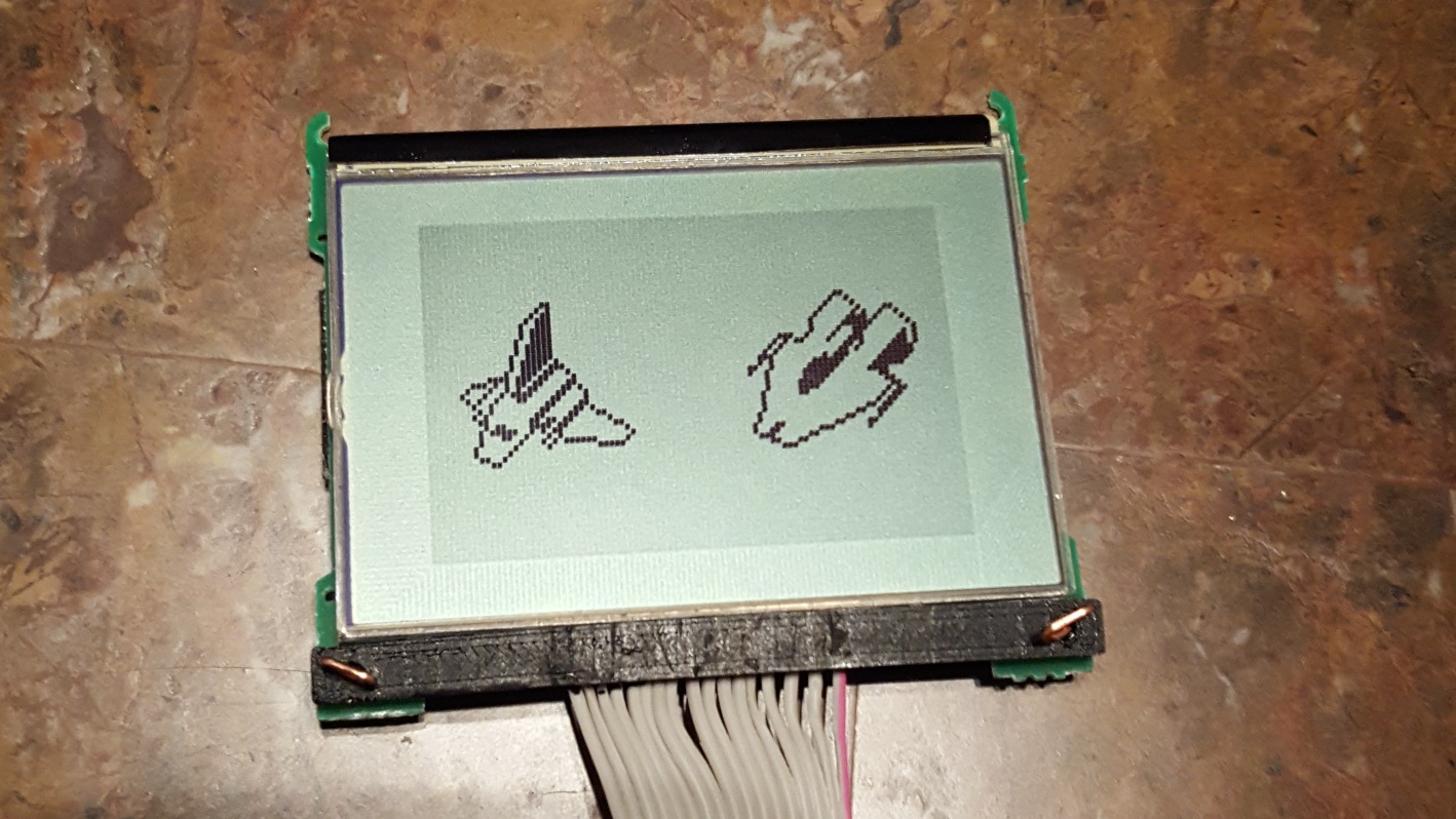
I did manage to get the pinout for this display (Overall I had to kind of brute-force the pinouts until something worked, as I couldn't find anyone with this specific display version online. Turns out it's a 17-pin interface with a Toshiba T6A04A driver chip, you can find the pinout and Arduino code here) and some skeleton Arduino code to get the display running.
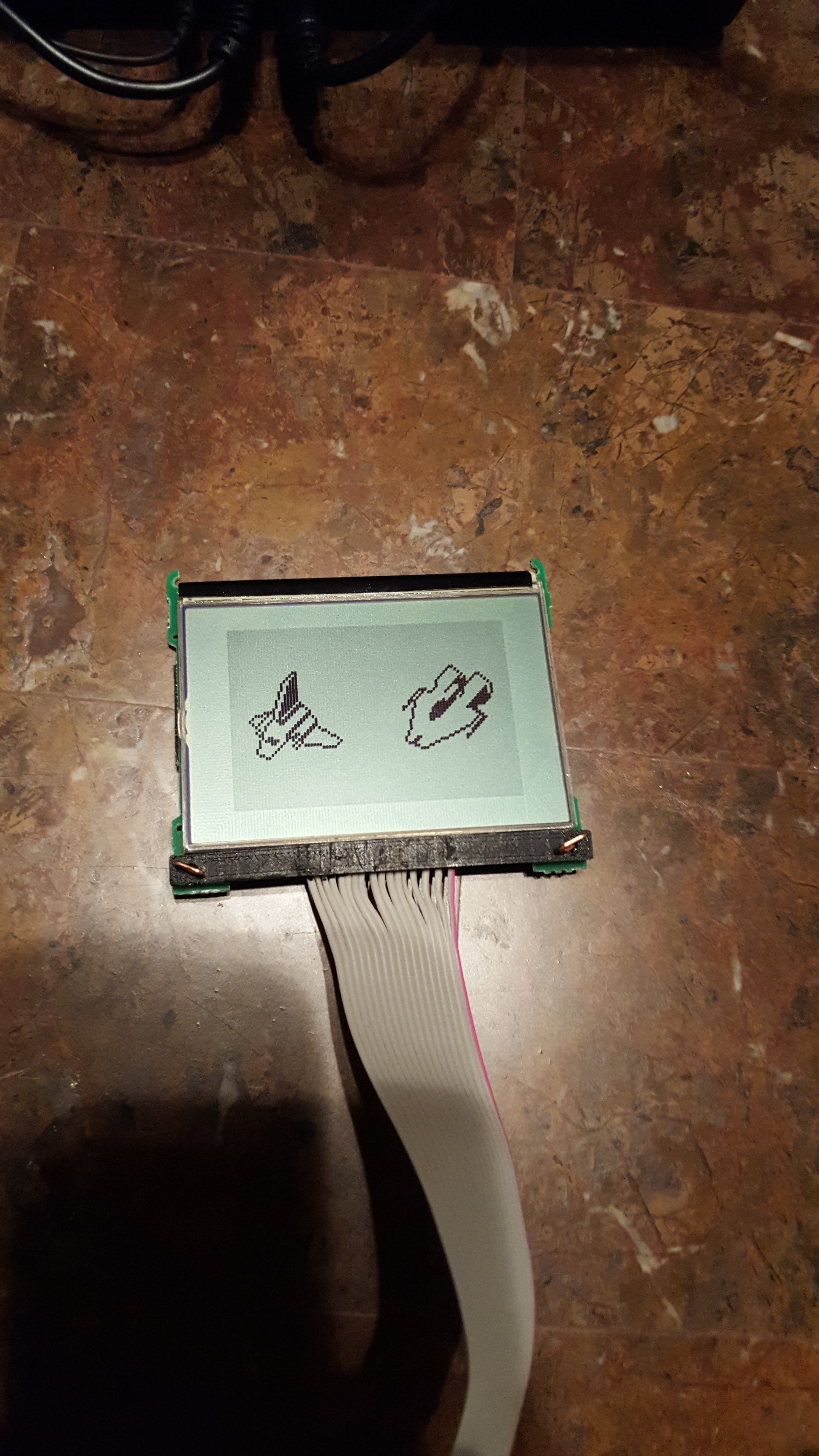
Note: I made that image with a tiny GUI utility I made in C# that exports all 96x64 pixels of the display into one big ol' array.
3: Code Port
The Arduino code was a success, but since C++ is not my forté, I got nothing truly done except displaying static images and updating the whole screen at once. That's no fun, since this is an LCD we're playing with, not a picture frame. I decided to port what I had of my code into C# for use with my Raspberry Pi, which is running Windows 10 IoT Core. The code is available on GitHub if you're interested.